During the Soviet Union, when there was a certain shortage of batteries, flashlights were very popular among the people, which did not require any batteries.
These were the so-called dynamo flashlights. The owner of the flashlight, like an expander, repeatedly pressed a special lever on the body. The generator located in the flashlight provided energy to the light bulb.
In the modern world, the production of such flashlights has not been stopped. The light bulb has been replaced with an LED, small-sized lithium-ion batteries are used to store electricity.
Today we will look at a flashlight that also works without batteries, but the owner of the flashlight does not need to press the lever to get power. It is enough just to shake the structure.
To make this flashlight, you will need the following items:
- copper wire with a diameter of 0.5mm
- round neodymium magnets with a diameter of 15mm and a thickness of 3mm
- metal-plastic tube with a diameter of 20mm
- diode bridge
- resistor 1 kΩ
- transistor KT 503 G or foreign analogue BC 637
- ionistor (supercapacitor) 1.5 F x 5.5 V
- LED with an operating voltage of 4.5-5 V
A wire with a diameter of 0.5 mm is wound on the tube. The number of turns is from 500 to 600.
Coil width - 30mm. The number of applied neodymium magnets is 10 pcs. When you connect the magnets one by one, the length of the assembly will also be 30 mm. The magnetic assembly is placed in the tube.
When you shake the tube with the coil lengthwise, the magnets will move inside the tube. When the magnets pass under the coil, emf will appear in its turns.
This energy will be used to power the LED.
At the ends of the tube you need to put plugs. To do this, you can use plywood - cut two circles with a diameter slightly smaller than the inner diameter of the tube. To soften the impact of the magnet on the plug, you can glue cotton wool to its inner surface.
For reliable fastening of the plug, it will be convenient to use hot glue.
Schematic diagram of a flashlight that works without batteries.
We connect the coil located on the tube to the diode bridge. At the output of the diode bridge, in accordance with the polarity, a supercapacitor (ionistor) is connected. As you have already noticed, its capacity is simply stunning - 1.5 Farad. The voltage generated at the ends of the coil is about 4.5 V. Therefore, the ionistor must be selected for a voltage of 5.5 V. If the generated voltage is greater than this value, reduce the number of turns.
Before arranging all the elements on the flashlight, assemble the circuit by surface mounting just on the table. Try her work.
The circuit should work without additional adjustment. Making sure it works. You can start mounting the circuit elements on the flashlight.
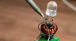
Using a heat gun, you can place all the elements along the tube. Or you can, as in the photo below - at the end of the tube.
To give the structure rigidity, and at the same time insulate the bare wires, fill everything with hot glue.
I almost forgot ... Between the common point of the primary with the secondary windings and the capacitor, install a switch.
Learn more about flashlight assembly: