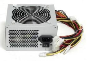
If you have an unused (but working) computer power supply, then you are almost the owner of a great car charger. Such a charger will have protection against overheating, overload, short circuit current. Rated load current - up to 10A (depending on the type of your PSU). The cost is only your time.
So, we need:
- Computer power supply.
- Soldering iron.
- Variable resistor about 100 kOhm.
- A fixed resistor, the value of which you yourself will select during the rework process.
- Multimeter.
- Power Supply Diagram - Desirable but not required
- Two hands, a mug of coffee or tea.
Understanding BP. All wires extending from the PSU can be safely unsoldered - they are no longer needed. But before that, find on the printed circuit board, in the places where these wires are connected, the designation (+12). If nothing is written on the board, we find this wire either by color coding (yellow wire) or with a multimeter. And do not forget to solder the green wire (it is the only one there) to the ground (the track to which the black wires were soldered). This is necessary to automatically start the PSU when it is turned on.
If you have already soldered the green wire to ground, plug the PSU into the network - it should turn on immediately. Turn off and look further.
Attention! Responsible moment! We find the largest microcircuit on the board (it may even be one). There is a reference resistance between the microcircuit and the soldering point of the Yellow wire (+12). It's what we need. If you didn’t find it right away along the tracks, download the diagram of your PSU and try to navigate along it. Below are a few PSU diagrams with these resistors marked.
Solder this resistor and measure its resistance. Instead, we solder a variable, having previously wound such a resistance on it, as in a soldered resistor.
We connect the multimeter to ground and contact (+12) in the DC voltage measurement mode. We put on a helmet or helmet of a motorcyclist - just in case. Turn on BP.
We look at the readings of the multimeter. The voltage should be from 11.5 to 12.5 V. Slowly rotate the resistor knob - we observe the voltage increase. Having reached the level of 14.4V, we turn it off. We solder the variable resistor and measure its resistance. We select a constant resistor for such a resistance. We solder it. Turn on - make sure that the voltage is about 14V.
Do not raise more than 14.5 V! Break the generation mode!
If you want to regulate the charging current, then you need to reduce the voltage to 10.5 V with a variable resistor and also measure its resistance. And solder into the circuit in series a constant resistor with a rating that was at 10 V, and a variable one - how many ohms are not enough to reach the level of 14 V.
Also replace the output capacitor (+12) with a similar one with a higher operating voltage.
For the information content of the charging process, add an ammeter. Rotate the fan so that air flows into the case and not out of the case.